EXERCISE 2
HEADS-UP DIGITIZING
FOR/GGR 525
BE SURE TO SAVE YOUR WORK REGULARLY!!!
 When editing a layer in
ArcMap, make sure you use the Save Edits option on the Editor toolbar to save
edits as a separate process from saving your map.
When editing a layer in
ArcMap, make sure you use the Save Edits option on the Editor toolbar to save
edits as a separate process from saving your map.
Due to some problems encountered in ArcMap when working on a network (the
software was not designed to transfer files across a network), you must copy
all of your working files to the C:\temp directory on the machine on
which you are currently working. This should be done with the
following procedure:
Close ArcCatalog and open Windows Explorer. Navigate to the C:\temp
directory, and create a new folder under the C:\temp directory called
"yourusernameggr525." For example, mine would be
"C:\temp\rcb28ggr525".
Copy and paste the tutorial folder from your Z drive into the C:\temp\"your
usernameggr525" folder. You should now have a folder named model in the
C:\temp\"your usernameggr525" folder that contains the coverages you
need, plus another folder named info. Remember to remove the read-only
attribute from these folders. This will allow you to save more quickly than
trying to write across the network.
Make sure you copy everything in your C:\temp\"your
usernameggr525" back to your Z:\ggr525\model folder when you are
done with your editing session, or you will loose all of the edits you have
made in this session!!! You must follow this procedure every
time you edit a coverage, or you will very likely not be able to save your
work!!!
INTRODUCTION
The purpose of this lab is to gain exposure to image data available on the
web, download it, and make vector features from the data. We will use the
polygon feature class to represent certain features around Flagstaff, like the NAU skydome and the
airport. We will use arc feature class to show roads, and the point feature
class to indicate buildings.
Download a Digital Orthophoto Quad to Digitize
- Download the FLAGSTAFF WEST SE Digital Orthophoto Quarter Quad (DOQQ) from
the Arizona Regional Image Archive (ARIA http://aria.arizona.edu/).
Be sure to get two files: a header .hdr and the image itself .tif. Be sure
to get the metadata, too. If you aren't sure which is the right file,
preview the image and right mouse-click to see the image name. Put the image
in your Z:for525/tutorial folder.
- Open ArcMap
 .
.
- Use the Add Data button
 to add the image you downloaded to the ArcMap TOC (Table of Contents).
- Click OK to build pyramids. This makes the image draw more quickly.
Create Two New Coverages to Hold the Digitized Features
- Leave ArcMap open, or minimize it, and open ArcCatalog
 .
.
- In your tutorial folder, use ArcCatalog to make two new coverages called fwsenet (for
flagwest
southeast network - network refers to polygons and arcs in the same dataset)
and fwsepnt. In making the coverages, use the following information:
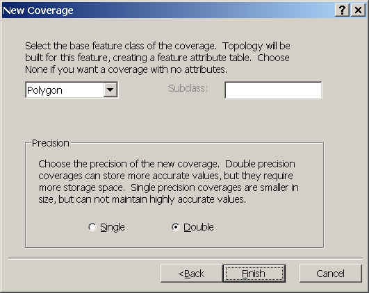
- Choose Base Feature Polygon for fwsenet and Base
Feature Point for fwsepnt. Refer to Exercise 1 if necessary.
We
never put points and polygons features in the same dataset because polygons
are referenced by their label point, which the computer does not distinguish
from a point.
- Define the coordinate system of the first new coverage
interactively, making the
projection definition the same as the DOQQ. If you did this on your own you
would have to extract the information from the DOQQ.
- Right mouse-click your DOQQ image layer in ArcCatalog.
- Choose Properties, and then select the Spatial Reference
tab.
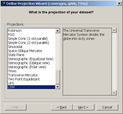
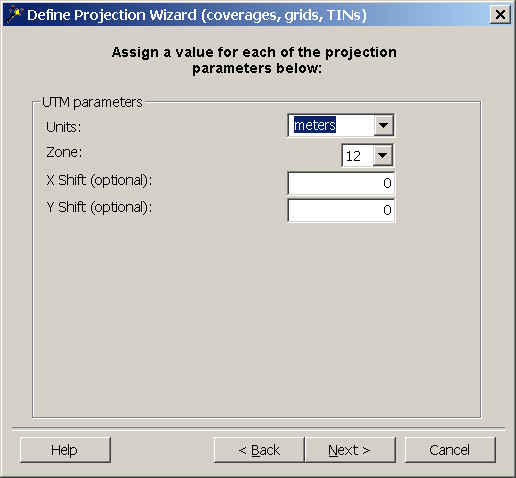
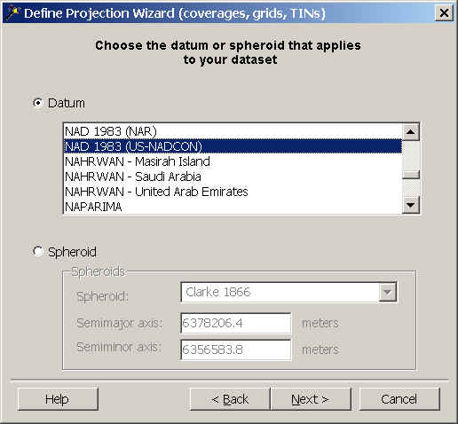
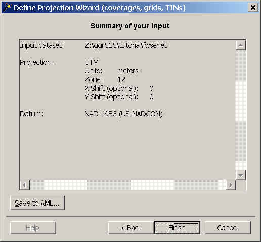
- Use the information you find under the Projection to enter the
proper information in the Define Projection Wizard for your fwsenet
and fwsepnt datasets. Be sure to choose the UTM Projection,
Units Meters, Zone 12, Datum NAD83 (US-NADCON), as shown below.
- Set the coordinate system of the second coverage the same as the
first.
Projection information is also accessible
in the Metadata, which can be accessed by in ArcCatalog by right
mouse-clicking the layer name and selecting the Metadata tab and then the
Spatial tab.
-
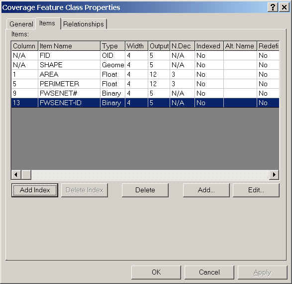
Open the fwsenet polygon attribute ( feature class) table (called a
pat) in ArcCatalog and add an item called Name by right clicking on the polygon
layer and selecting "Properties".
-
Do the same for the the fwsepnt point feature
class.
-
When you created the 'Net' coverage, the feature class you chose was
Polygon. This creates a Polygon Attribute Table, which has one record for
every polygon in the coverage. If we want to add attributes to the lines
(e.g. the names of roads), we have to have ArcMap build an arc (line)
attribute table (or aat). Do this next:
-
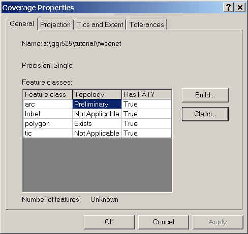
Right mouse-click fwsenet in ArcCatalog and choose Properties.
-
Click the General tab.
-
Under the column Has FAT?, Feature Class Arc says False. This means there is
no Feature Attribute Table associated with the arcs. Highlight the arc
feature class and choose Build to make one. In the Build window change the
Feature Class pulldown to Line. Click OK. Now it should say True under Has
FAT?.
-
Close ArcCatalog.
-
Now you should be able to add a Name field to the Arc layer of fswenet.
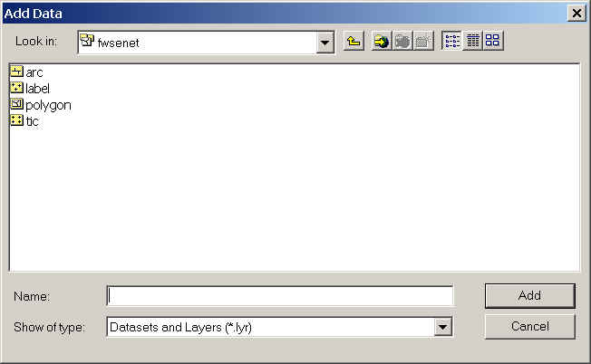
- Next, add the two new coverages to your ArcMap map using
.
Be sure to add all the layers of the fwsenet coverage by
double-clicking the coverage name in the browse window and including the
poly, arc, and label layers.
If you are unable to add the
Name field, close your ArcMap session and try again. ArcGIS is very careful about
not allowing a file in use to be changed, and sometimes it gets a little
confused about which files are in use.
You could also choose to make
two separate coverages, one for the polygons, and one for the arcs, instead of
putting them in one coverage as we have here.
Digitize (draw) the Features
- Open the editor toolbar
 and choose Start Editing.
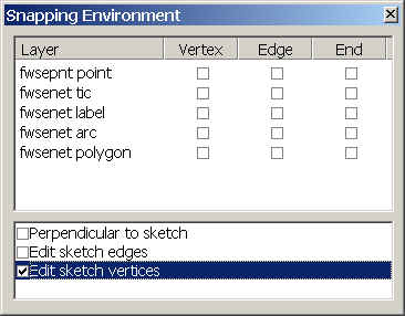
- Always start the digitizing process by setting the snapping environment.
From the Editor pulldown menu
 choose Snapping.... We want to be able to snap vertices
of our sketch, so turn this function on.
choose Snapping.... We want to be able to snap vertices
of our sketch, so turn this function on.
- First we will draw polygons.
- Click the Current Task dropdown arrow and click
Create New Feature.
- Click the Target layer dropdown arrow and the fwsenet
polygon layer.
- Click the tool palette dropdown arrow
 from the Editor toolbar and select the Sketch tool
 .
.
- Draw (digitize) polygons for the NAU SkyDome, the airport and two other
areas of choice on the DOQQ by clicking on the map to digitize the first polygon's vertices. When
finished, right-click anywhere on the map and click Finish Sketch (or press
F2).
Use the tools on the Tools
toolbar to zoom in and out of the image, and move to areas you want to view.
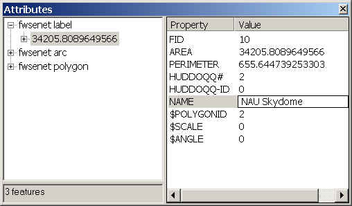
- Edit the feature class attributes (tabular data) as you go by pressing the Attributes button
 on the edit toolbar, then click in the Name field, and type in the name of
the feature.
on the edit toolbar, then click in the Name field, and type in the name of
the feature.
- When polygons are complete, choose fwsenet arc as the target
layer. Draw arcs for I-17, I-40, and Lake Mary Road. Be sure to add the name
of the road to the attributes.
- When arcs are complete, choose fwsepnt point as the target layer.
Add points in the center of 10 familiar buildings on the NAU campus. Be sure
to add the names to the attributes.
- Your lab TA will explain the process of creating a layout, and you will
turn in a layout showing your digitized polygons.
- Save the map.
- Be happy you did not have to use the digitizing tablet!
 Return to Class Home Page...